p5.projection
Easy projection mapping for p5js
p5.projection.js is a library
that hopes makes it easy to map a p5js sketch onto a projected
surface to correct for 3D shapes, projector mis-alignment or
even moving surfaces. It requires four uv coordinates and four
xy coordinates to create the sixteen values for applyMatrix()
that will make the projected image line up with the real world.
For many applications it is enough to click on the four corners
of the projected image and map those to the canvas coordinates
(0,0), (1920,0), (1920,1080) and (0,1080), then call into the
update() function to compute the forward and inverse matrices.
Inspired by OpenCV perspectiveTransform()
Getting started
Include math.js and p5.projection.js in your code and create ProjectionMatrix object.
In your setup() function create a WEBGL canvas and in your draw() function,
call mat.apply() to skew the drawing to the projected frame. You can add a mouseClicked()
to update the mat.outPts array with the correct corners.
<html>
  <head>
    <script src="https://cdnjs.cloudflare.com/ajax/libs/p5.js/1.3.1/p5.js"></script>
    <script src="https://cdnjs.cloudflare.com/ajax/libs/mathjs/9.5.1/math.js"></script>
    <script src="https://cdn.jsdelivr.net/gh/osresearch/p5.projection@0.2.1/library/p5.projection.js"></script>
  </head>
  <body>
<script>
let mat = new ProjectionMatrix();

function setup()
{
	createCanvas(windowWidth-10, windowHeight-10, WEBGL);
	mat.edit = true;
}

function draw()
{
	background(0);

	mat.apply();

	fill(80);
	stroke(150);
	strokeWeight(2);
	rect(400, 200, 200, 200);
	rect(600, 200, 200, 200);
	rect(800, 200, 200, 200);
	rect(800, 400, 200, 200);
	rect(600, 600, 200, 200);
}
</script>
</body>
</html>
Examples
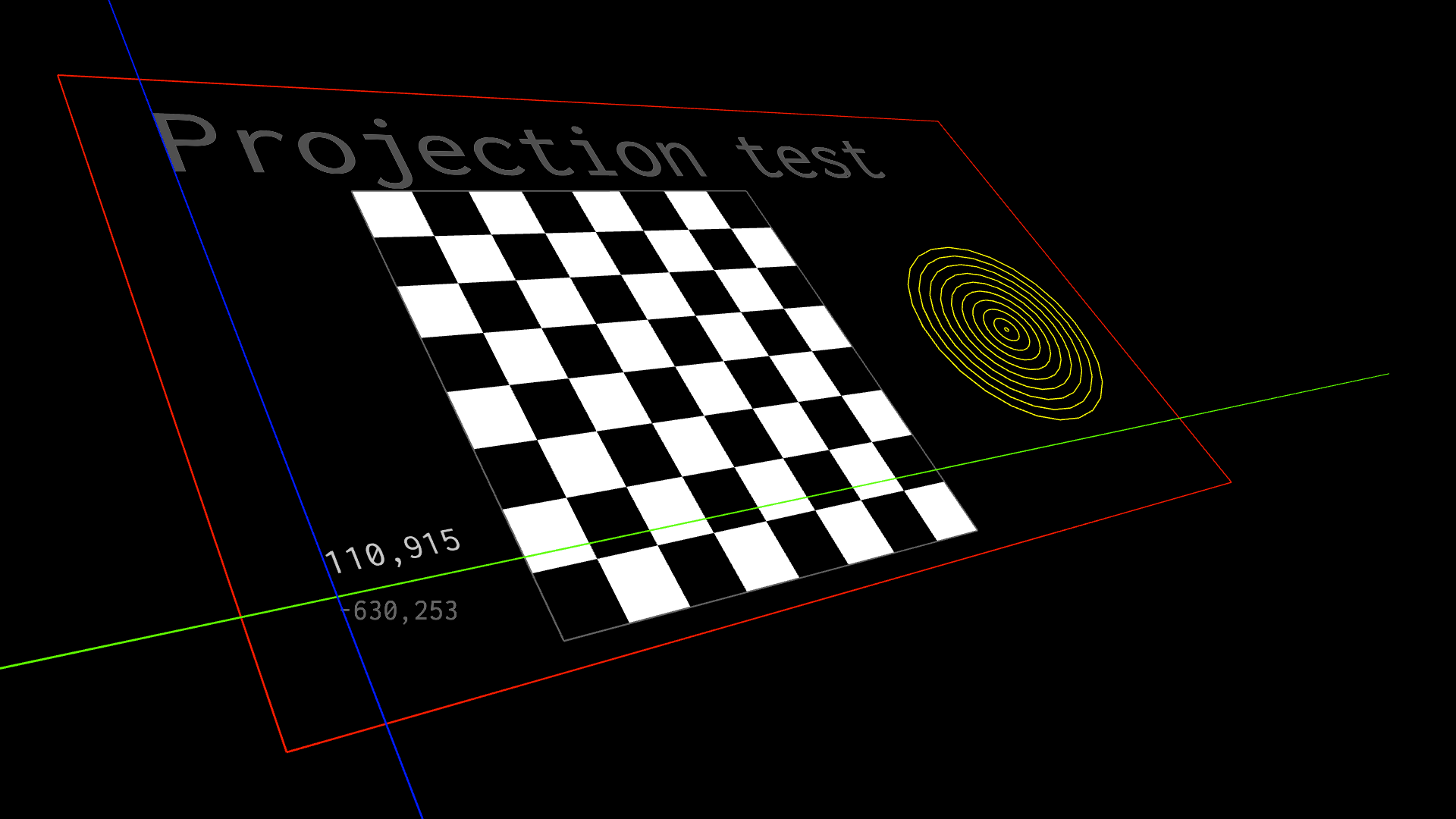
Chessboard example shows how to translate screen coordinates into canvas coordinates and back, as well as demonstrates line drawing and fonts in the projection mapping mode.
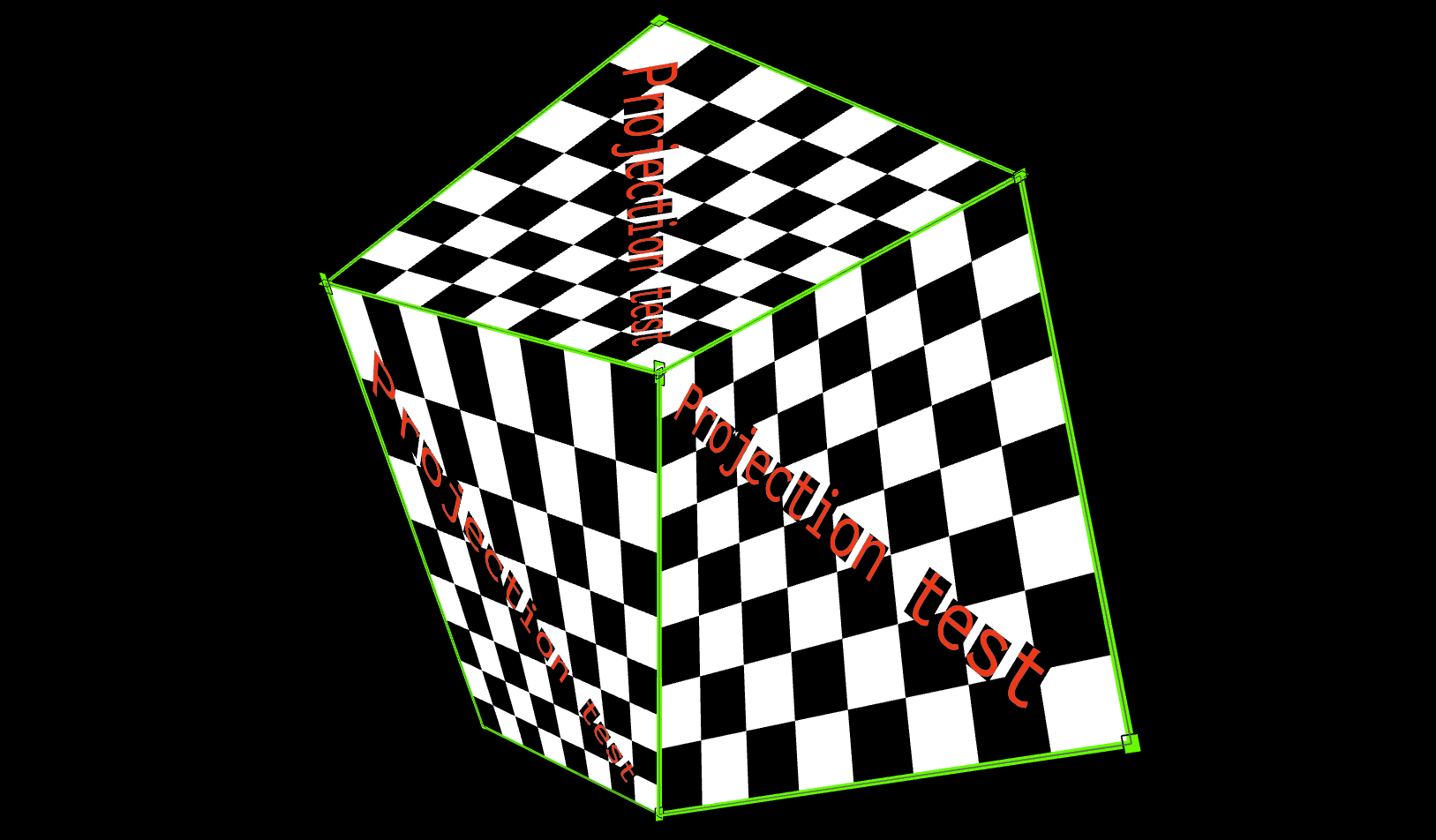
Multiple projected surfaces on a cube shows how multiple
ProjectionMatrix objects can be created to allow mapping to multiple real world
surfaces, such as onto the three visible faces of a cube.
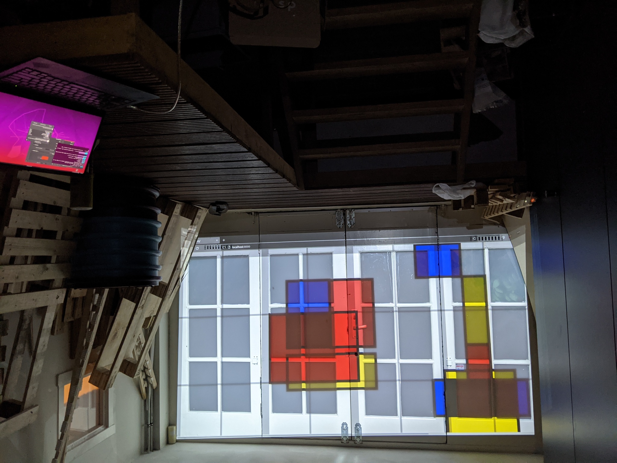
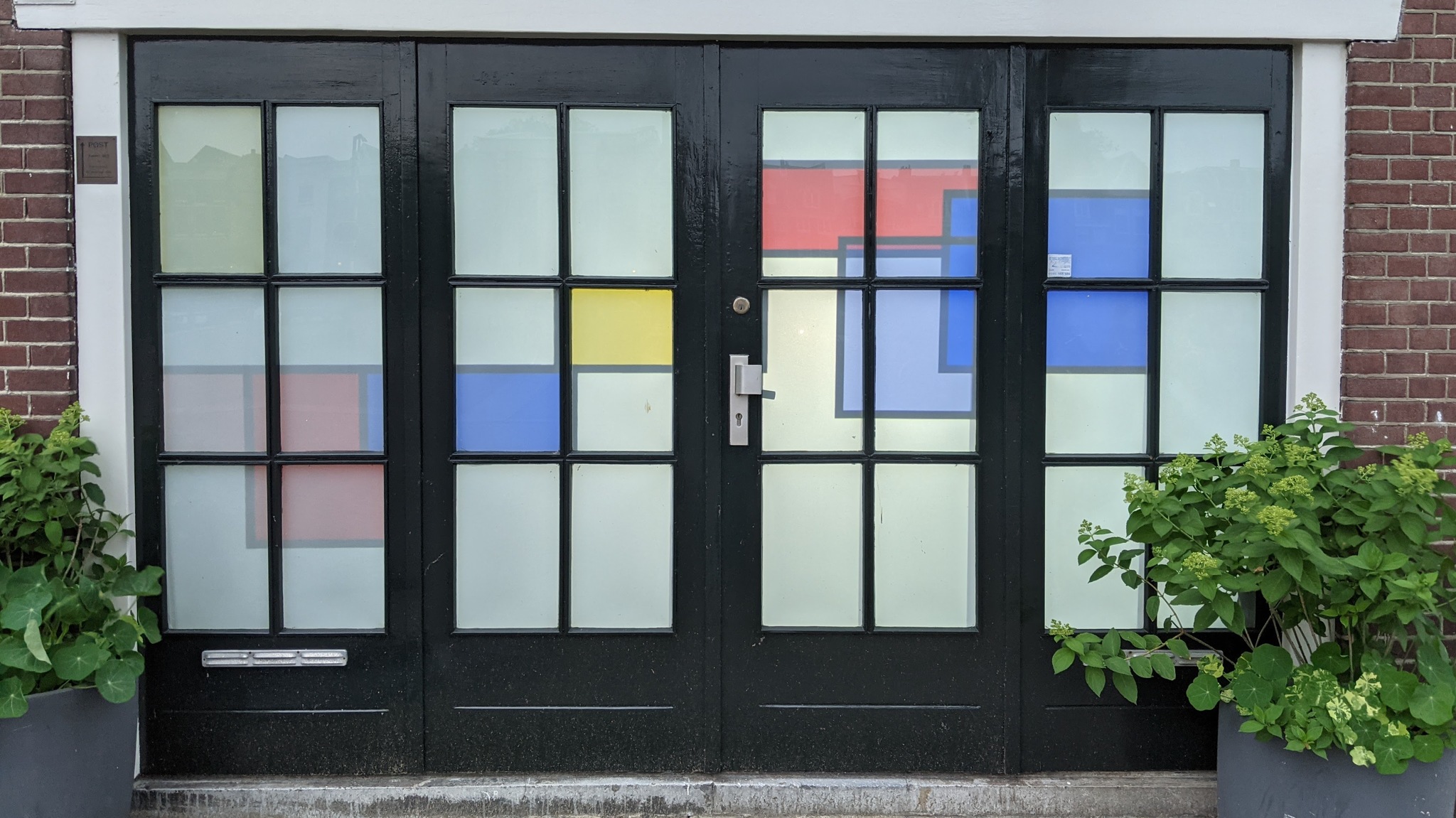 Mondrian art rear-projected on glass doors.
This was the art installation that started this project.
Mondrian art rear-projected on glass doors.
This was the art installation that started this project.
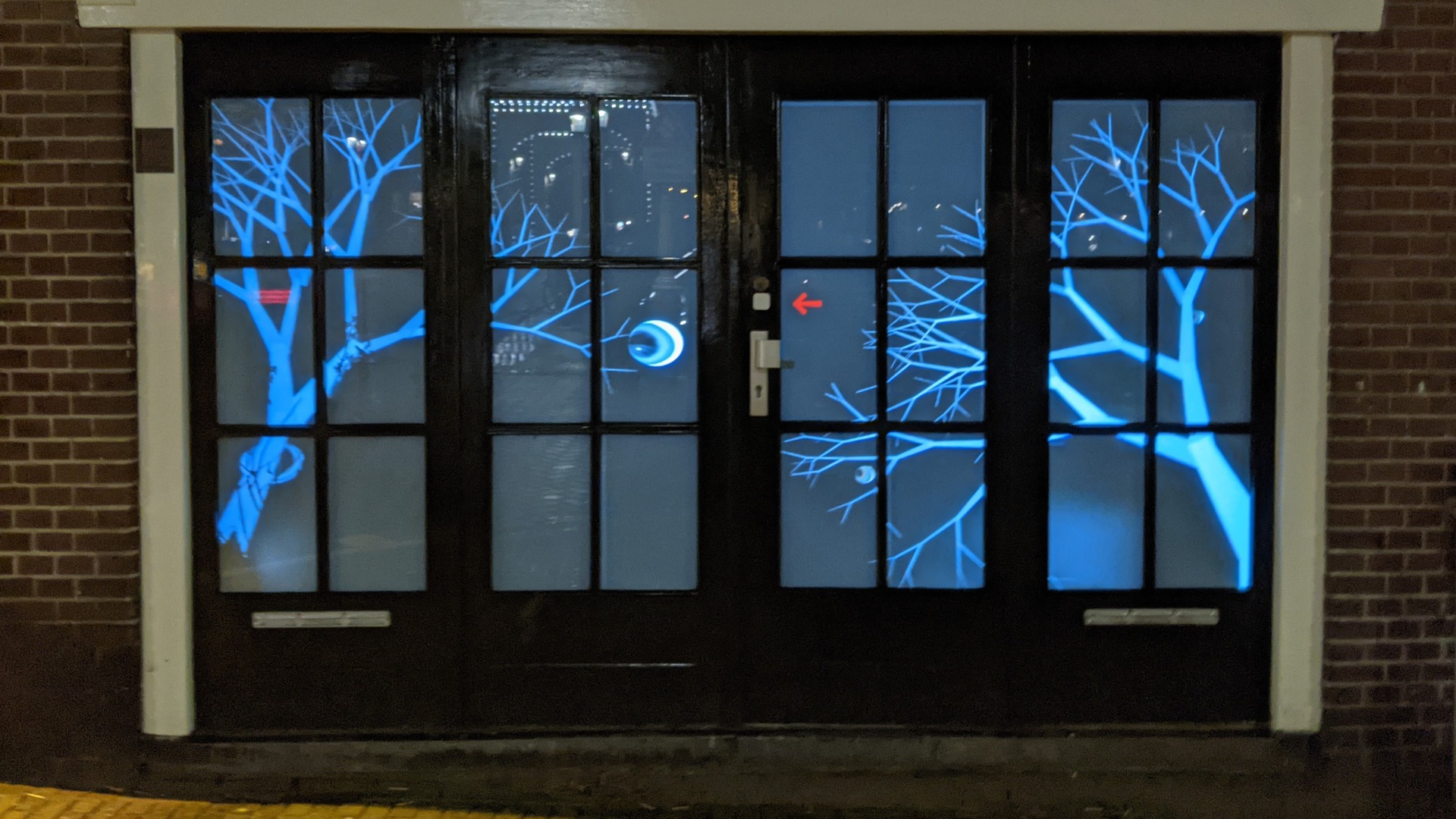
Halloween trees and eyeballs, on the same glass doors.
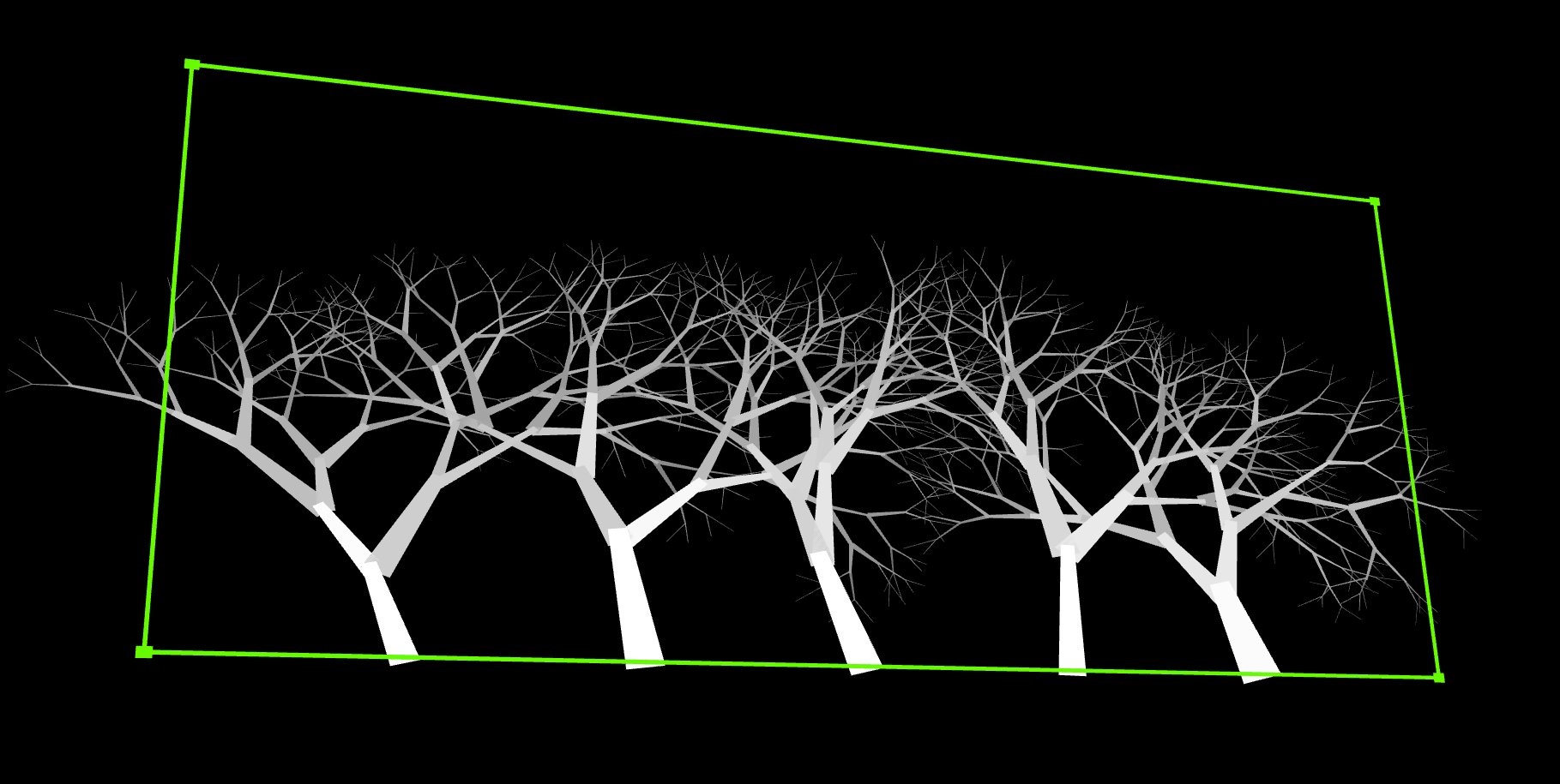
Just the fractal trees, which slowly wave in a creepy way, blown by the GPU fan that spins up to draw all those line segments.
The math parts
You don’t need to understand this part to use the library, although you might find it interesting to see how it works under the covers.
The XY drawing coordinates are translated into UV screen coordinates
using a normal perspective transform matrix C that maps from (x,y)
to (u,v,z) space through C xy = uvz:
/ c00 c01 c02 \   / x \    / u \
| c10 c11 c12 | * | y |  = | v |
\ c20 c21 1   /   \ 1 /    \ z /
Multiplying the matrix and applying the perspective transform to make u and v
shrink towards the center as they get further away from the “camera”:
 zi =  c20*xi + c21*yi + 1
 ui = (c00*xi + c01*yi + c02) / zi
 vi = (c10*xi + c11*yi + c12) / zi
The problem is how to find the eight variable entries in the C matrix
so that the xy points correctly map to output real-world coordinates
in uv space. Since the library takes in four xy points and four corresponding
uv points, this is eight knowns which should uniquely map to the eight
unknowns.
To make it easier to solve, it is best to rewrite the uv equations and
expand them out so that the variables are isolated.
 ui * zi = c00*xi + c01*yi + c02
 vi * zi = c10*xi + c11*yi + c12
Each of these can be expanded
 ui * (c20*xi + c21*yi + 1) = c00*xi + c01*yi + c02
 c20*(ui*xi) + c21*(ui*yi) + ui = c00*xi + c01*yi + c02
 ui = c00*xi + c01*yi + c02 - c20*(ui*xi) - c21*(ui*yi)
and
 vi * (c20*xi + c21*yi + 1) = c10*xi + c11*yi + c12
 c20*(vi*xi) + c21*(vi*yi) + vi = c10*xi + c11*yi + c12
 vi = c10*xi + c11*yi + c12 - c20*(vi*xi) - c21*(vi*yi)
These eight equations can now be written as:
 u0 = c00*x0 + c01*y0 + c02 - c20*(u0*x0) - c21*(u0*y0)
 u1 = c00*x1 + c01*y1 + c02 - c20*(u1*x1) - c21*(u1*y1)
 u2 = c00*x2 + c01*y2 + c02 - c20*(u2*x2) - c21*(u2*y2)
 u3 = c00*x3 + c01*y3 + c02 - c20*(u3*x3) - c21*(u3*y3)
 v0 = c10*x0 + c11*y0 + c12 - c20*(v0*x0) - c21*(v0*y0)
 v1 = c10*x1 + c11*y1 + c12 - c20*(v1*x1) - c21*(v1*y1)
 v2 = c10*x2 + c11*y2 + c12 - c20*(v2*x2) - c21*(v2*y2)
 v3 = c10*x3 + c11*y3 + c12 - c20*(v3*x3) - c21*(v3*y3)
This is the linear system:
 / x0 y0  1  0  0  0 -x0*u0 -y0*u0 \ /c00\ /u0\
 | x1 y1  1  0  0  0 -x1*u1 -y1*u1 | |c01| |u1|
 | x2 y2  1  0  0  0 -x2*u2 -y2*u2 | |c02| |u2|
 | x3 y3  1  0  0  0 -x3*u3 -y3*u3 |.|c10|=|u3|
 |  0  0  0 x0 y0  1 -x0*v0 -y0*v0 | |c11| |v0|
 |  0  0  0 x1 y1  1 -x1*v1 -y1*v1 | |c12| |v1|
 |  0  0  0 x2 y2  1 -x2*v2 -y2*v2 | |c20| |v2|
 \  0  0  0 x3 y3  1 -x3*v3 -y3*v3 / \c21/ \v3/
The variables c_ij can be computed by inverting the 8x8 matrix,
or using math.js function lusolve().
The WebGL parts
The p5 applyMatrix()
takes either 6 elements, in which case only affine transforms are supported,
or 16 elements, which allows arbitrary XYZ to UVW projections.
Since the 2D values have z=0, the equation that the matrix should apply is:
 ui = c00*xi + c01*yi + 0*zi + c02
 vi = c10*xi + c11*yi + 0*zi + c12
 zi = c20*xi + c21*yi + 0*zi + 1
This means that the columns of the arguments to applyMatrix()
must be c00, c01, 0, c02, c10, c11, 0, c12, and c20, c21, 0, 1:
	applyMatrix(
		mat[0], mat[3], 0, mat[6],
		mat[1], mat[4], 0, mat[7],
		0,      0,      1, 0,
		mat[2], mat[5], 0, mat[8]);
The helper function applies this matrix for the caller.